Saturday 6 April 2013

Run Lock

Introduction

First it may be important to explain what run lock is, and where it can be useful.
Run lock allows the car to continue running even when the ignition keys have been removed, then and depending on how it has been set up if the handbrake or any of the pedals are pressed it will cut out the engine, and the car cant be restarted until the key is put back into the ignition.

This allows the car to run with the engine on and possibly the doors locked, but if anyone tries to drive off they get a nasty surprise in that the car will not drive.

Runlock is used mainly by the emergency services to keep their vehicles running at the roadside if they were switched off their batteries would drain very quickly. However for the ordinary motorist it is useful for preventing frost jacking, this is when you turn your car on to defrost and go back to the house for something and in that time someone steals it, with run lock its not possible to steal the car.

Its ok to use run lock if the car is on your own driveway, but as for using it in public places legally it is a bit of a grey area, it is worth reading this:
http://www.enginerunlock.com/Run_Lock_Legality.htm
However this still should suit most people who want to safely let their car run on their own driveway.


The Run Lock Kit

I purchased the run lock kit from this site:
http://www.enginerunlock.com

Basically all it contained was a relay, a switch, some in line fuse holders, connectors, and it was already wired together. The instructions that come with it are probably the most valuable bit, and they actually sell the instructions as a single item for people who want to make the complete kit themselves.

A few days later it arrived and i installed it following the instructions, if you have a multimeter and know how to use it then instalation of the relay is very easy.

(testing out the kit after wiring it to the ignition key

Handbrake Switch

This kit intends for you to have it deactivate with the handbrake switch, this is where i had to become a bit inventive, because on multiplexed 406's the wiring isnt a simple case of the handbrake switch connecting a warning light to the bodys ground/earth, in the 406 its connected to the BSI

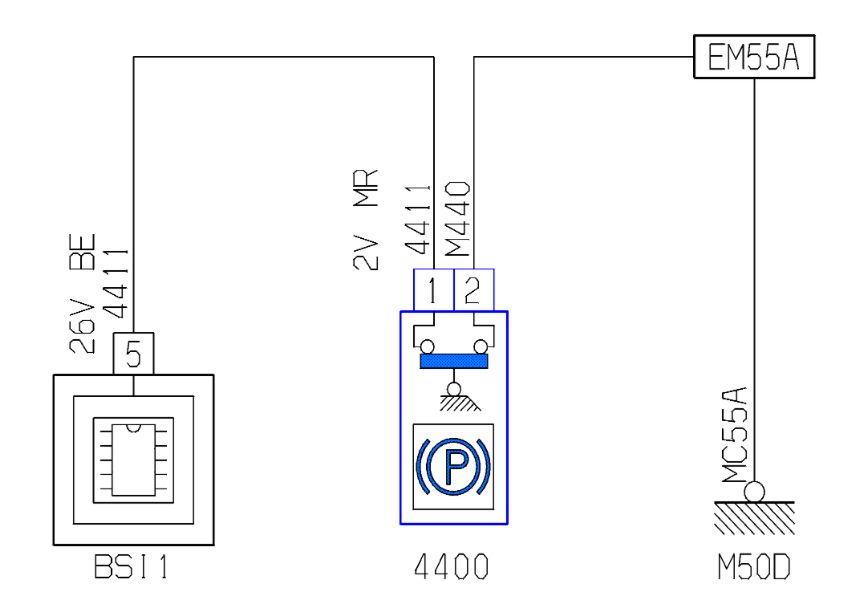
a wiring diagram showing the handbrake switch
(406 wiring diagrams are available from: http://petrila.net/peugeot/Service/index.htm

From past experience of wiring round the 406 anything added to the BSI can make it go mad and all the cars electrics will act strange or possibly not at all.
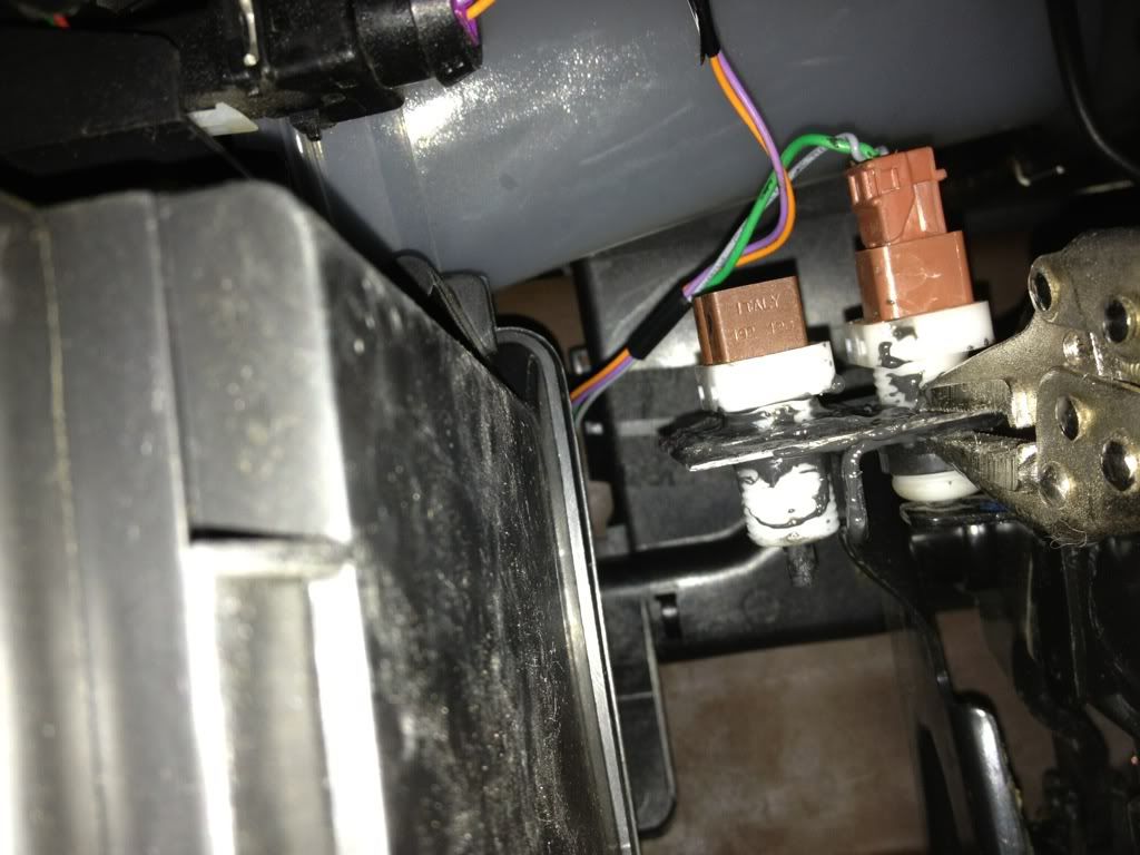
Therefore i decided to put in a seperate handbrake switch just for the run lock, to make it i got a spare 406 handbrake switch, the easiest place to get one is the glovebox switch out of a 406 in a scrapyard, when removing it keep the connector plug and a decent bit of wire which makes wiring it up to the run lock easier.

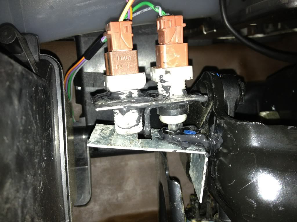
Here was the handbrake area before adding in the second switch:


I made a bracket to hold this switch out of some spare tin that i had when welding a hole on the subaru,
to get a rough idea of the shape required for the bracket i used card first and tried it for size, this is easier than cutting metal. Once the card template was right i used a dremel and cut off wheel to precisely cut the metal, here was the bracket with the switch installed onto the car beside the original handbrake switch, as well as the striker plate to push the switch down, both parts were glued into place with JB weld:


(note the loose wire was there to test the connection at the time, all connections were soldered and heatshrink tubing applied over them)


The wiring of the switch was very simple one wire was given a ring crimp connector and that was bolted onto the nearest earth point, the second wire went to the ground wire on the run lock kit, therefore when the handbrake was up the switch provided the run lock circuit with a ground connection and allowed the car to run, when the handbrake was put down the connection was broken and the car turned off.

In order to see how to remove the centre console to get to the handbrake switch this video is available:


Clutch Switch

At this stage everything was put back together and the run lock system worked, the car would run with the key out of the ignition but when the handbrake was set down it turned off. However on the 406 the handbrake is notoriously terrible, and even though the steering lock would engage there was nothing to stop the potential thief putting the car in gear and moving it, so i decided to improve the system by adding a switch to the clutch pedal.

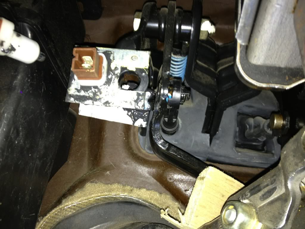
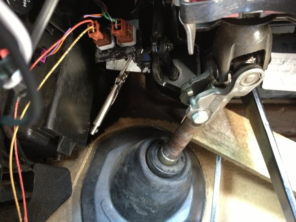
The clutch pedal on my 406 has already got a cruise control switch on it, but like the handbrake switch the clutch switch is connected to the BSI so to avoid problems a second switch was to be added just for the run lock. The area to work in round the clutch is much more cramped and awkward than the handbrake area, this involved some uncomfortable positions trying to look at the area, as with the handbrake switch card was used to measure out the profile required for the clutch switch bracket, and just as importantly the striker plate, which was just a flat bit of metal on the handbrake, here it would have to be correctly shaped to clear obstacles in the area, here is the area before the addition of any extra switches:


The switch required was one that when pushed closed would be on, and when out would be off, a push to make switch, the direct opposite of the handbrakes push to break switch. However that is exactly what the crusie control switch does so i purchased another cruise control switch for £6.

Below shows the switch bracket and striker plate:

(the switch is held onto the bracket by the fact the hole cut is tightly cut, and the JB weld)

(the connection at the back for 2 wires is the same as the connection at the back of a 406 handbrake or glovebox lid switch, thankfully my attic is full of these connectors)

(the striker plate, the hole in the fold is so that the striker plate does not come into contact with a spot weld on the clutch pedal and thus it can sit flat)

(when making any of these parts it can be a case of trial and error, constantly checking that the parts fit correctly and do not interfere with moving parts)


The switch brakcet was the first part to be put into place, it was glued beside the original cruise control switch:

(JB weld was used again to hold this part in place, note the vice grips which were used to hold the part while the JB weld dried)

With the switch bracket in place and the JB weld dried, the next part was to add the striker plate, however because normally the cluch pedal is held up against the switch it had to be held away so the striker plate could be put in place and the JB weld allowed to dry. To hold the clutch pedal back an old piece of timber was used and the striker plate was stuck into place:


(the striker plate was glued onto the back of the original clutch pedal striker plate, a different type of vice grips were used to hold it in place wile the JB weld dried)

After waiting for a few hours to allow the JB weld to dry, the piece of wood was removed and the clutch peal brought back to it natural position, the striker plate made contact with the switch and the mutimeter confirmed it was on:


(time was taken to ensure this extra switch did not make any odd noises when the clutch was used, and that the original cruise control switch was not affected or altered in any way.)

With it working wiring the switch up was a simple case of interrupting the earth supply to the handbrake switch, therefore if either the handbrake was down or the clutch pressed in the car would turn off.

With this done the car was put back together:

Run lock switch

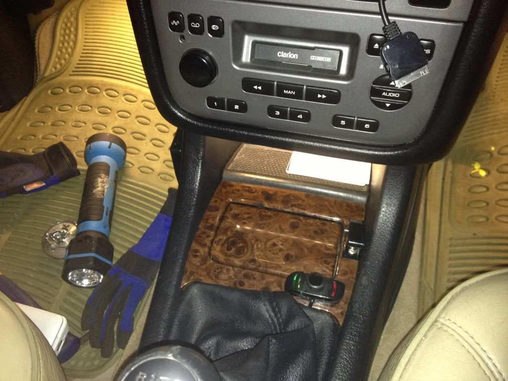
The instructions show how to wire up everything and the switch supplied in the kit has 3 wires going to it, its up to you to decide where to position it, however i decided that the best place was beside the ash tray, this is an easy panel to mount it to as its flat and ergonomically easy to reach.
Another reason for selecting this location is that replacing the ash tray is relatively easy if the car is to be returned to standard. Below shows the switch closed then in use:
(note it is the black switch with the cover the other switch in this area is the one which operates the hands free system)
(this is the switch turned on with the red light to show that the run lock is activated)

The Run Lock in Operation

To see the operation of the run lock there are 2 videos, one of the run lock before adding the clutch switch, the other after it was added:


Conclusion

Run lock is an easy kit to add to a car, even cars like this with an immobiliser, the challenge can be in working out is it safe to wire to an existing handbrake or clutch switch and if not as was the case here then being able to add extra switches.
I have done this mainly as an experiment to see if it was possible to add run lock to a multiplexed 406 and it is indeed possible, i live in the countryside so its normally safe enough to leave my car around the house with the keys in it, but if you live in a suburban area and have your car running on your driveway to defrost it in the morning then this is a great kit to avoid worrying about someone stealing your car.

Update

The bracket holding the extra clutch switch in place fell off today, the JB weld didn't stick to anything on the car side, the reason was there is a plastic ring on most of the area and JB weld didn't stick too well to the plastic, in all other areas it was sticking metal to metal which it does fine. I therefore used small pop rivets to hold the bracket in place:


(you can see in this picture with the main cruise control switch out of the way that the area is mostly occupied by the plastic ring which holds the cruise control switch in place therefore the JB weld had nothing really to stick to, the pop rivets are holding the bracket into solid metal and are holding the bracket in place very strongly)


Tuesday 25 December 2012

DIY Parking Sensor Installation 


This is a guide to installing an ebay parking sensor kit on a 2002 Peugeot 406 Saloon. It should apply to all saloons, and it an easy and cheap addition to the car.
This kit cost less than £30 and bar a mistake i made with painting they are very accurate sensors, i had them on my old fiat panda, and renault clio which worked very well, the clio has had them for 4 years and they still work without a problem.

The first issue is to find a place to place the parking sensor ECU, it needs to be close to the rear bumper, and it needs power from the reverse light, handily in the boot of the 406 each corner of the boot has ample space.

After removing the carpet on the right hand side of the boot, i found the JBL amp, and located the ecu on top of that, on other models without the amp there should be even more space, some double sided sticky tape and cable ties is what i used to secure the ecu in place:

ECU Placement and Power Supply:

This shows the best location to place the ecu, some cars have nothing here, some have this amp, some can also have a sat nav drive, regardless of that there should still be plenty of room to fit the ecu.

 Some double sided sticky tape under the ECU should help it stick into place

The power to the ECU comes from the parking sensors, i removed the plug going to the rear light cluster, and used a multimeter to find which wire sent power to the reverse light and spliced into that for the positive feed, i used the cars body to provide the earth/negative.
Note: the blue connector i used failed after about 2 months, i recommend soldering the wires together and sealing it with heat shrink as a more reliable connection:

Another view of the wiring, the power is supplied, i found a tidy place to mount the bleeper, make sure you can hear it, its plug just slots into the ecu. As you can see cable ties are the handiest way to reinforce the double sided sticky tape:


Drilling out holes


Now the next thing to do is drill the holes for the parking sensors, its the scary bit because you cant undrill holes in your bumper. I did not use a particularly accurate way of measuring the best place to drill the holes, just along the bottom lip of the bumper, this is great because there is over 30mm of flat surface to work with, the sensors have a diameter of 21 so more than plenty of flat surface to work with. Also behind this part of the bumper there is no obstructions such as impact bars.

To measure where to put the sensors as i mentioned is tricky, i got a pair of identical chairs, set them at each side of the car, i tied a string level between the two chairs which dealt with the horzontal placement. As for the vertical i measured from the ground up (the ground being a flat shed floor, and the car had nothing in the boot that would leave the suspension sitting to one side)
I used the centre of the towbar to measure the distance the sensors should be to each side of it, the first pair of sensors were below the corner of the tailight, and the second pair of sensors i got the left on to below the 'P' in Peugeot, measuered the distance and did the same on the other side.

It might be an odd way to measure, it worked for me, your free to try your own technique. Measuring this sort of thing is my least favourite bit.
With the 4 points selected with a bit of black marker i used a punch to make a small indent in the bumper, and drilled out the holes with the drill bit supplied with the sensors. Its 21mm so precisley whats needed for the sensors, and as the bumper is a soft material a basic cordless drill will get through it easily

Below shows the supplied drill bit drilling through the bumper, which leaves a neat and tidy cut that is ready to accept the sensor:

These arrows point to where i placed the parking sensors on the rear bumper:

Putting the sensors into the bumper:

With the holes drilled the next step is to put the sensors into the bumper, this is simple, slide the spacer ring through the wires and up to the sensor (easier now than later) then thread the wires through the bumper, and put the sensor into the bumper.

The spacers are shaped to give you some control over the angle the sensors face at, which is useful given that the bit of bumper the sensors were mounted onto faces upwards. The spacers correct this and keep the sensors pointed behind the car.
The spacers can be a bit hard to slide over the sensor and this is where a ruler or flat edge is handy to push them on without breaking them:

Put the wires for the sensors through the bumper first, they are also labeled A,B,C,D on the sensors, i started with A on the left side of the car, and D on the right, i dont acutally think the sensors are any different but it does no harm to put them in order:

Push the sensors on ahead into the bumper, twist them to have them facing at the right angle, then push them into the bumper good and tight:

This shows what the sensors look like from behind the bumper, its only a bit of foam that provides a tight fit to hold the sensors in, however i have had them on 2 years now and they have not fell out.

Painting the sensors:

If you buy the sensors in most cases you can choose to get the right colour from the seller, i had these matte black sensors from a car i never put them into, so i had to paint them.

I will show you how to paint them, im not good at painting things, and its probably best to get them the right colour in the first place to save the hassle, and also i found after painting the sensors (a job i actually did 2 weeks after the installation) that the sensors which worked perfectly became over sensitive indicated that the car was too close to something even when it wasn't near anything.

Anyhow here goes, The area got well masked off:

Then i thought the masking wouldnt prevent overspary well enough, so i put the sensors into these cardboard boxes to prevent overspray even better. (Now im typing this guide it would have made more sense to have taken the sensors out of the car again and sprayed them away from the car, but this was what was done):

The carboard boxes again, which worked superbly well at preventing overspray, and they also could be   closed over while the paint was drying to prevent dust getting on the paint:

The Painted Sensors:

Depending on the paint makers instructions let the paint dry, i was using the genuine Peugeot spray paint for the sensors, with two coats of lacquer (the lacquer is probably what ruined the accuracy of the sensors) However they were well painted. 
Once dried i pushed the sensors back into the bumper:

Routing the parking sensor wires:

The next job is to get the wires from the 4 sensors to the ECU in the boot of the car, the first job is to drill a hole to let the wires come into the car. You might find a unused grommet, or be able to take the bumper off and find a suitable hole. However i decided to drill a new hole.

I drilled out the new hole in the area near the parking sensor ECU, i used the 21mm drill bit to cut a hole through the boot floor. It took longer to drill the hole than the plastic but the bit did the job no problem. As you can see below, i drilled from underneath the car upwards, therefore i knew i wasnt drilling into some reinforcement bar, the wire beside it goes to the trailer lights plug:

I made sure to apply a liberal amount of Galvanising paint to both sides of this hole to prevent rust, i painted it on with a brush, not too many will see this part of the car to care about brush strokes:

I put an old grommet round the hole to stop the wires getting cut on the sharp metal, then routed the wires for the 4 sensors under the car through this hole and into the boot. The wires have plenty of length. Be careful when routing the wires, make sure to secure them tight to something solid thankfully the towbar bracket was a handy place to wrap cable ties around, its also worth taking into account the exhaust gets hot so make sure none of the wires get close enough to the exhaust to melt.
With the wires nicely routed under the car and secured by cable ties, bring them up into the car, i then put a good dollop of silicone into the hole to keep it sealed:

Now bring the 4 wires up to the ecu, plug them into the correct sockets, the Lables on the end of each wire say A,B,C,D and they meet up with the labled sockets on the ECU. It probably doesnt matter so much on this simple ECU where the wires are plugged in, but on more sophisticaed parking sensor systems with an LCD display plugging the sensors in correctly would make sure the display shows weather the obstruction was coming from the left or right. 
Here are the wires going into the ECU:

Tuck the wires neatly into place, there is a lot of excess wire, i didnt want to cut them because the wee plugs look flimsy, and I dont even know if they can be cut and shortened correctly (the instructions may have said not to cut the sensor wires). Anyhow i tidied up the 4 wires and put the boot carpet back in place, its impossible to see any of the wires or ECU with the carpet back in place:

The Finished Sensors:

The sensors worked great before i painted them, after painting as i said they would scream that something was behind the car when there wasn't, its worse in the wet. Given the cheap cost of a kit i really should buy already coloured sensors and plonk them into place, the ECU can stay as most parking sensor kits off ebay are the same.

Here is the installed sensors: